 For security or breach thereof.
1996 Yamaha Seca II
(a.k.a. XJ600)
By Jeremy Reeder, Certified Professional Locksith. © 2009 The Safe House. Originally published in Keynotes, Volume 55, Issue 6, June 2009.
Okay, class, today we’ll be examining, from a locksmith perspective, a nice red motorcycle known as the Yamaha Seca II, or XJ600. Figure 1 shows this beautiful bike, along with its lucky owner.
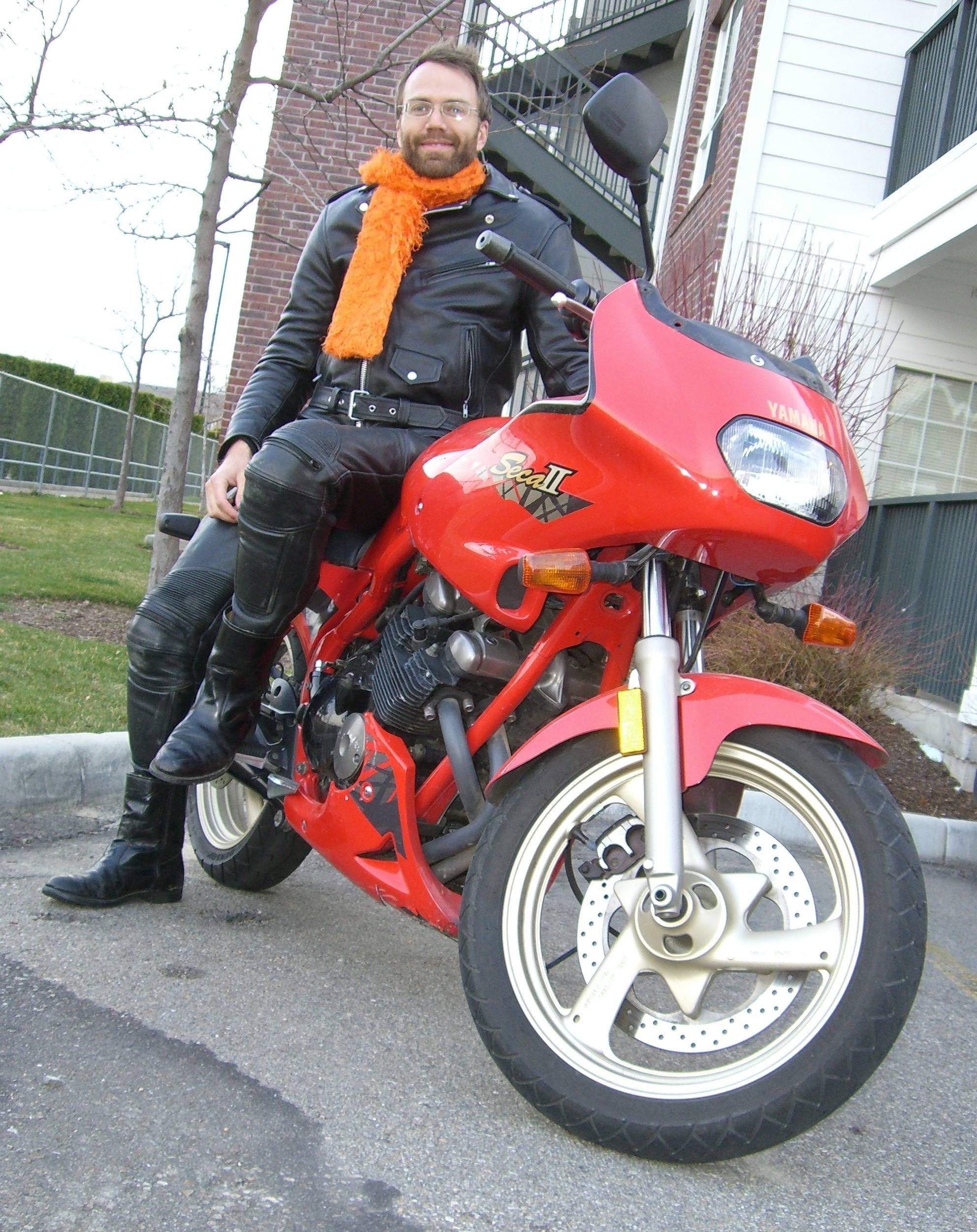 Figure 1
This is a 600-cc sport-touring bike, and I recently had the privilege of borrowing it for a day. I took it for a nice little ride, of course, using it as my grocery-getter to transport bolts, bearings, and miscellaneous gizmos that I needed for some safecracking tools.
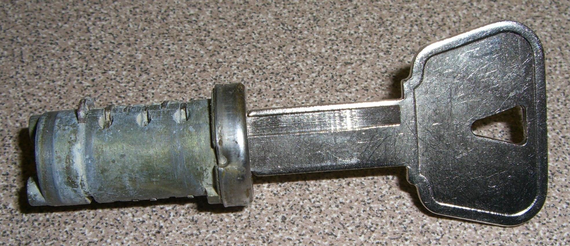
But I also couldn’t resist examining the locks on this bike while I had it in my possession. There are three locks on this bike: the gas-tank lock, the seat/helmet lock, and the ignition lock. All three locks use the same key, which can be created from an Ilco X248/YM63 key-blank.
Gas-Tank Lock
The first lock I disassembled was the gas-tank lock. This is usually the lock that I disassemble when I need to make keys for a sportbike. The first step, using a 4-mm allen wrench, is to remove the three visible socket-head screws that hold the gas-cap to the tank. These are the front-most and the two rear-most of the seven visible screws. The other four visible screws are relatively short and serve no purpose other than adornment. There’s also one hidden screw that will be addressed later.
The next step is to open the gas cap. This is done by lifting the keyhole-cover, aligning the wafer-tumblers with a pick, rotating the plug clockwise, and lifting the door. These locks are no harder to pick than the simplest of wafer-tumbler locks. Once the lock is picked and rotated slightly, however, I sometimes have to use a screwdriver to apply enough torque to the plug to retract the spring-loaded latch.
The third step is to remove the hidden socket-head screw. Well, it’s not so hidden anymore, but it was when the gas-cap door was closed. This black screw, near the hinge, is now the only fastener holding the gas-cap to the tank. Figure 2 shows this hidden screw being removed. Now lift the entire gas-cap assembly off the tank. Then plug the gas-cap so that no nasties get in the gas-tank. I used a clean leather glove for this purpose.
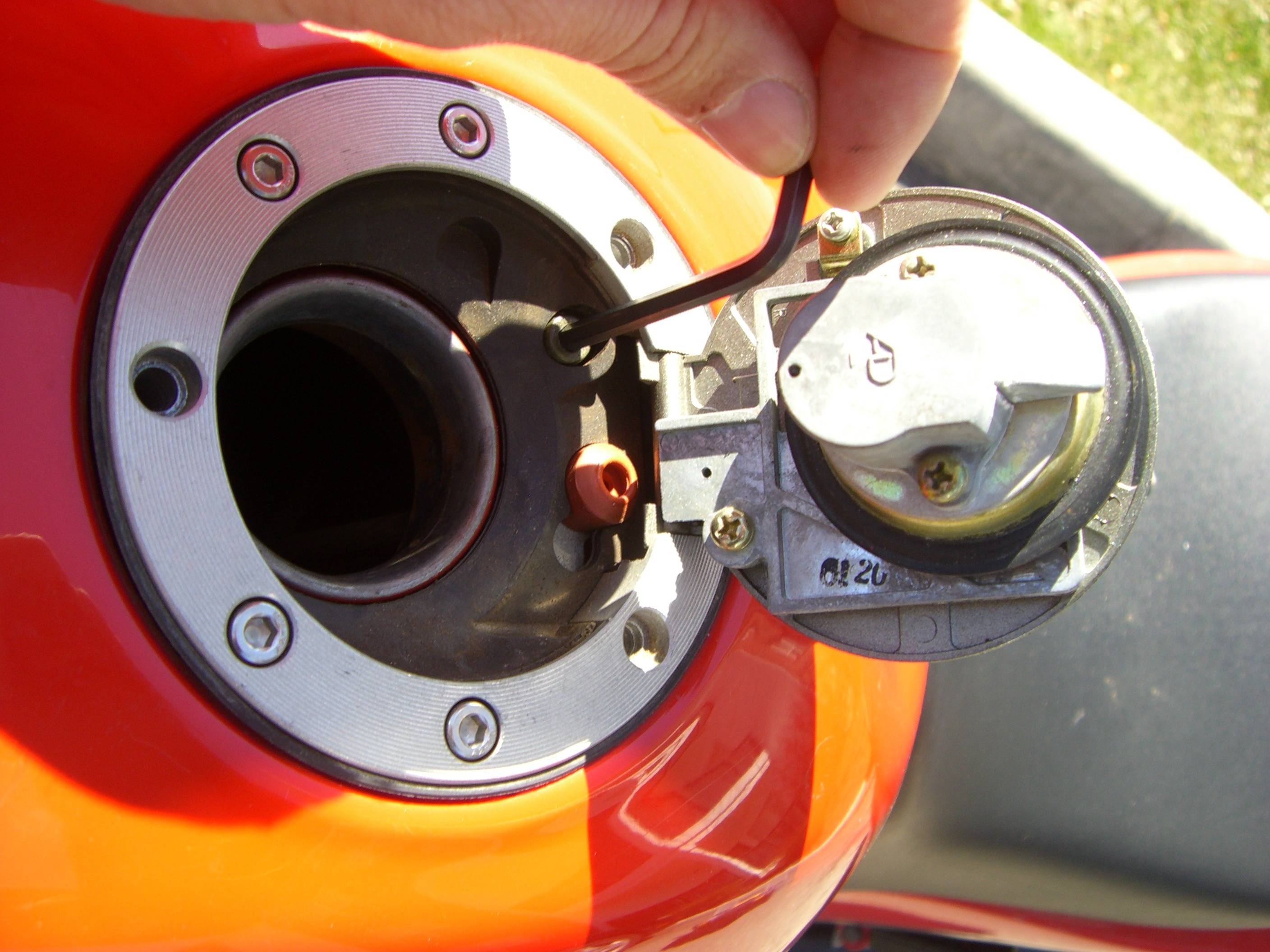 Figure 2
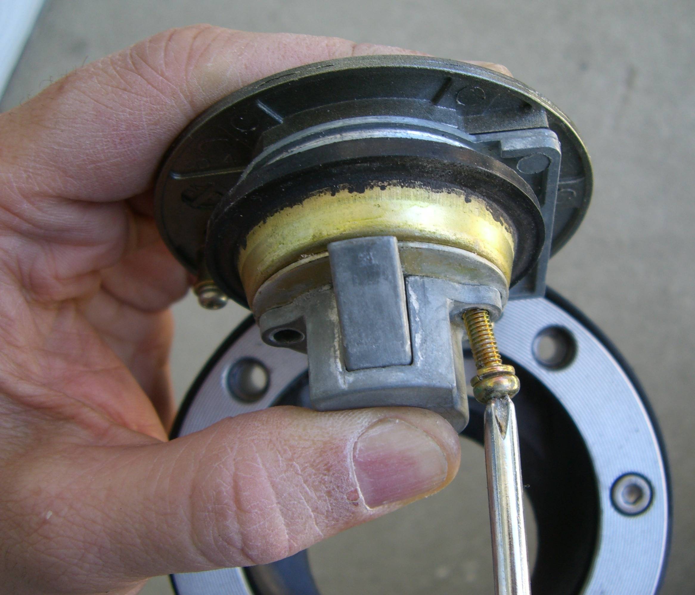
Next we remove the latch assembly and the plate and collar behind it, as seen in figure 3. This is all held on by two phillips screws. Beneath the collar are four springs, seen in figure 4. Remove the springs, and then remove the lock cylinder, which is held on by the two phillips screws seen in figure 5.
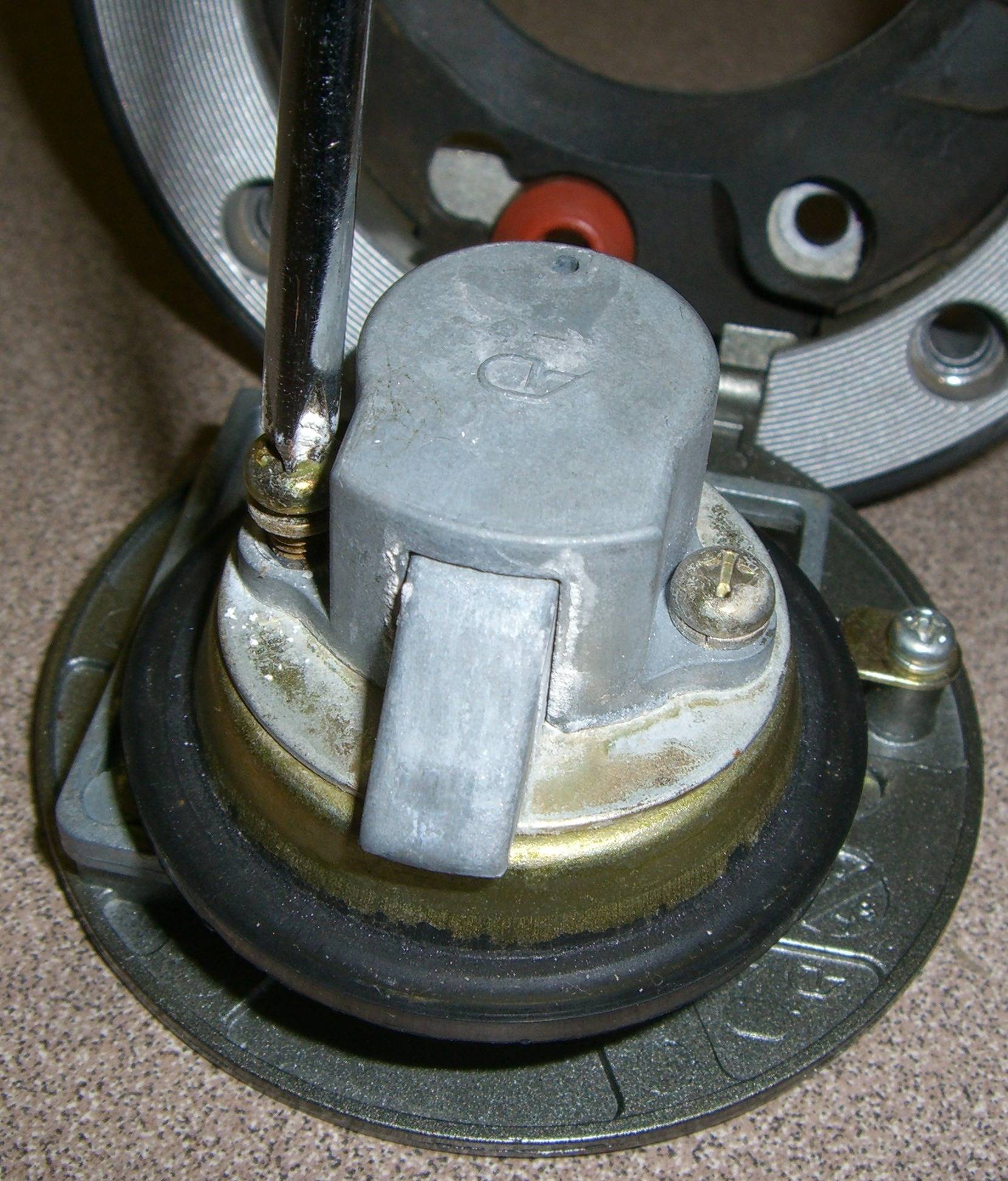
 Figures 3 thru 5
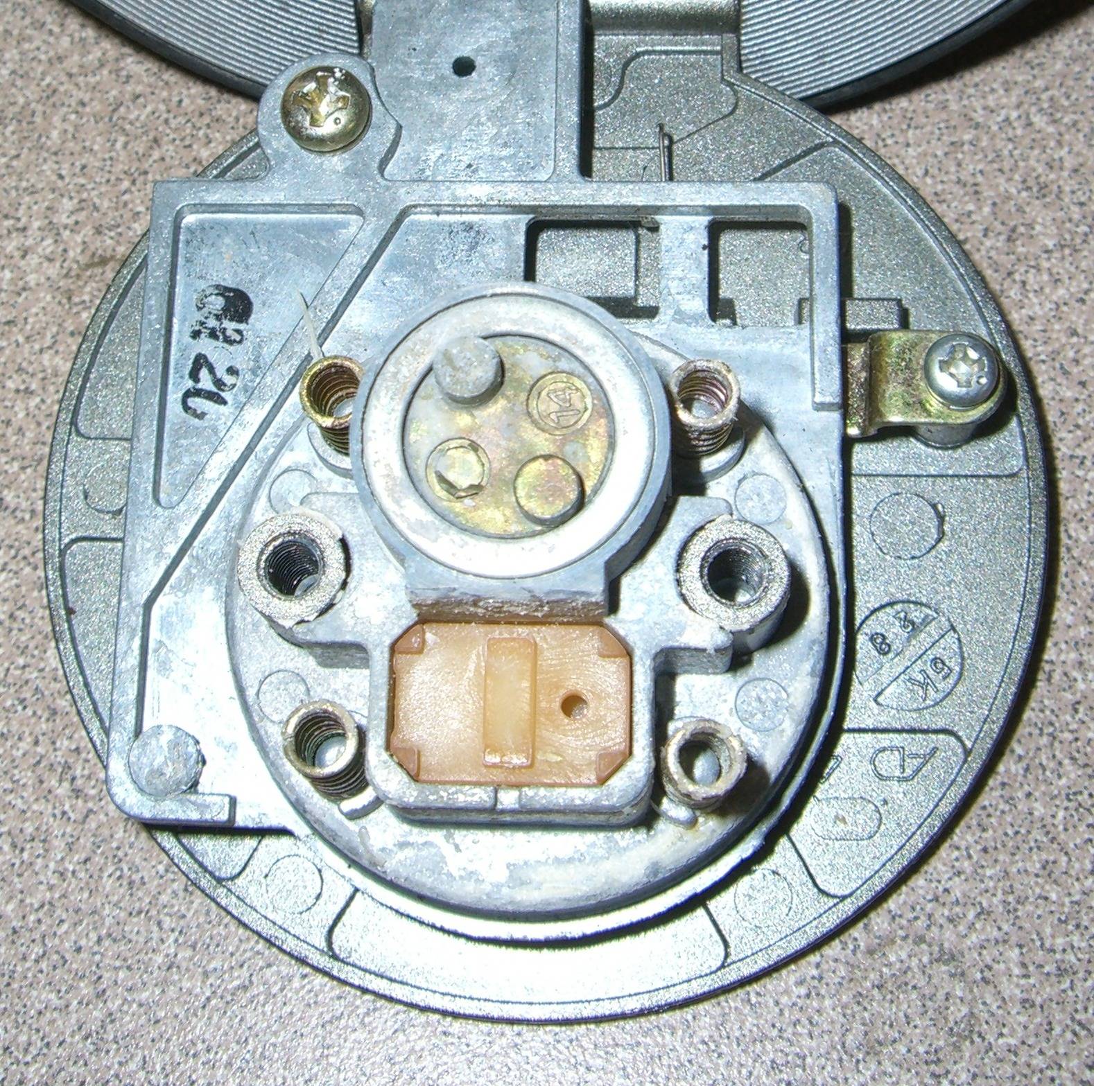
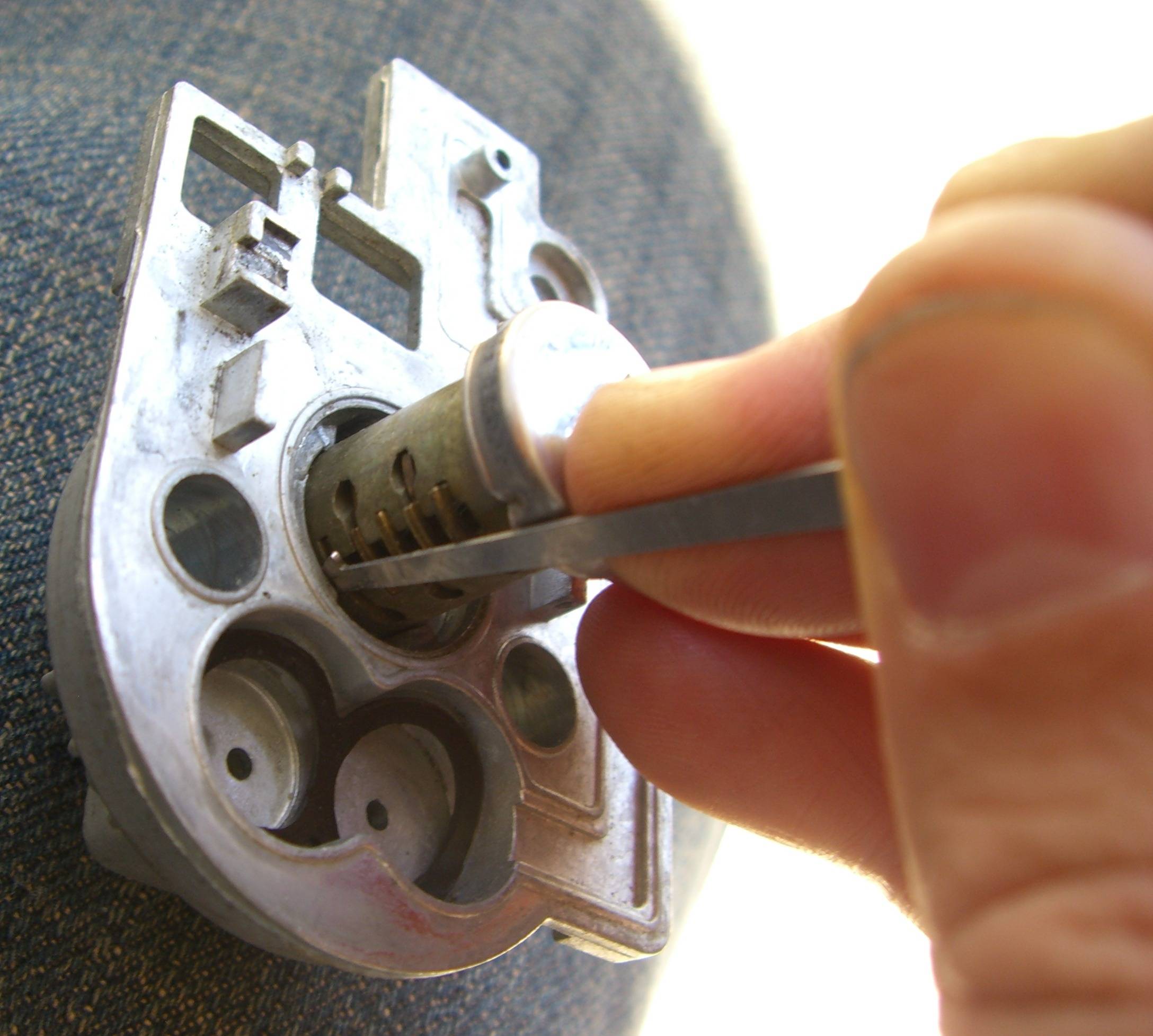
This lock cylinder’s retainer-wafer is shaped such that it can not be retracted through the key-hole as the wafer-tumblers can. Otherwise we wouldn’t have needed to go to all this trouble. But, with a metal ring, an O-ring, and another metal ring below it all removed from the lock cylinder, we have direct access to push the retainer-wafer into the plug. Figure 6 shows the O-ring being pried up with a lock-pick, and figure 7 shows the retainer-wafer. I pushed the retainer-wafer in with a lock-pick and then used a finger to press the plug out of the cylinder as in figure 8.
 Figures 6 thru 8
With the plug removed, we can see the five wafer-tumblers clearly, so it becomes easy to make a key that properly aligns them. The plug is shown in figure 9 with a key that properly aligns these tumblers, whereas the retainer-wafer remains extended. Note that they are aligned by the five cuts closest to the tip of the key, whereas the key will ultimately need a total of seven cuts.
Holding all six wafers inside the plug with a lock-pick, I inserted the plug back in the shell as in figure 10. The plug stop must be within its path of travel, but the tumblers should not be aligned with the shell’s plug-chambers. This way, the retainer-wafer will not re-extend until the plug is fully inserted. That is why the plug is shown slightly clockwise of its locked orientation.
Reassembly and re-installation of the gas-cap are the reverse of the disassembly and removal processes, respectively. Note that the various parts must be held in place against spring-force, as in figure 11, until they are fastened. This gas-tank lock is typical of sport-bikes and sport-touring bikes in general.
 Figures 9 thru 11
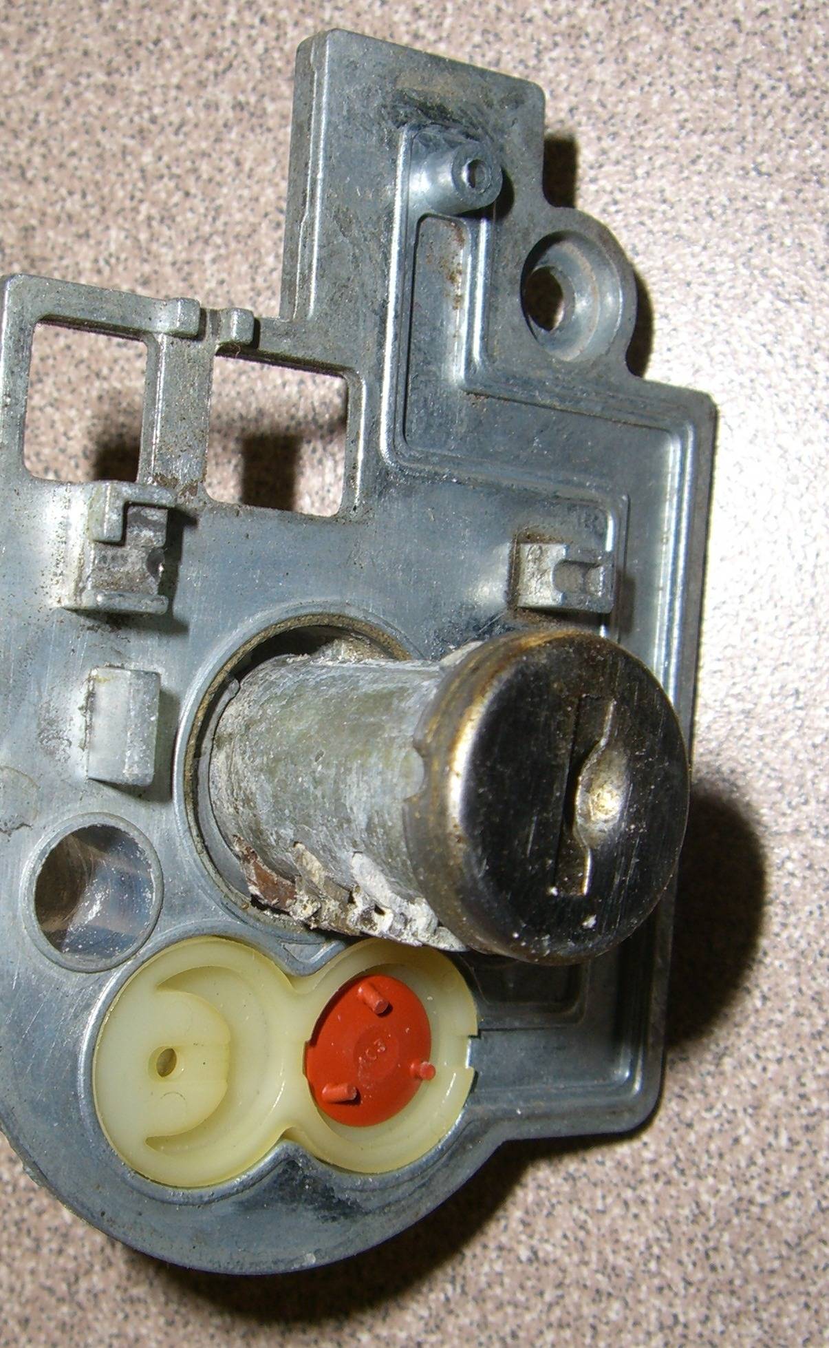
Seat/Helmet Lock
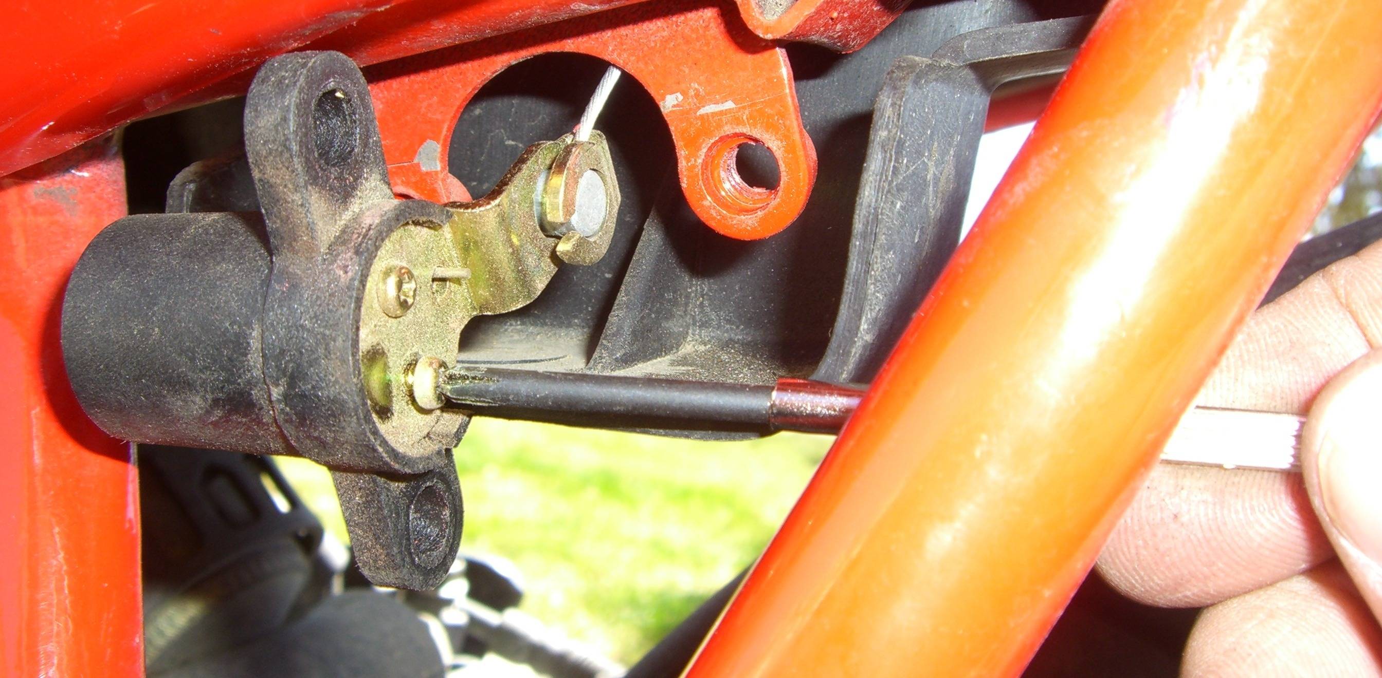
Now for the seat lock. This is a very easy lock to deal with, and it gives us exactly the same information that the gas-tank lock gives. Just like the gas-tank lock, this is a wafer-tumbler lock using the five cuts of the key that are closest to the key’s tip. I often find that seat locks and helmet locks have fewer tumblers than gas-tank locks, and that’s why I go for the latter. But there’s no advantage to that approach in this case.
The lock is held onto the frame of the bike by two Torx screws. The proper tool is, of course, a Torx screwdriver; but I used a 4-mm allen wrench and a cheater-bar instead, as pictured in figure 12. It did the trick.
 Figures 12 thru 14
The cam attached to the back of the lock operates the latch by pulling a cable. On locks like this, I leave the cam attached to the cable and simply unfasten it from the lock cylinder. The cam is held on the cable with two small phillips screws, one of which is being removed in figure 13.
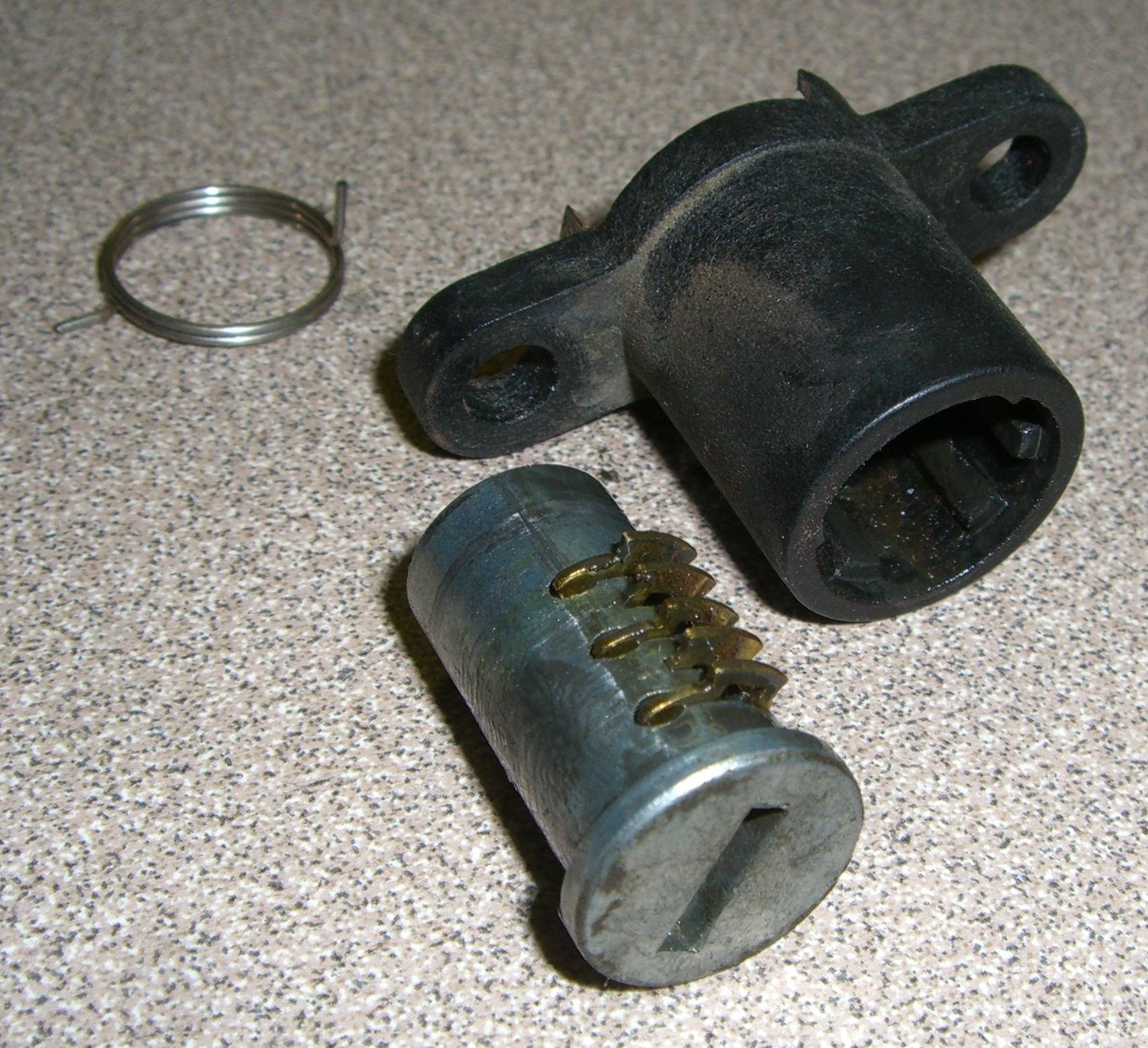
That leaves three major parts to the lock, as seen in figure 14: the plug (with five wafer-tumblers and five springs), the shell, and the spring that returns the plug to the locked position. The shell slides right out the front of the shell. A key can now be easily made for this plug just as for the plug of the gas-tank lock.
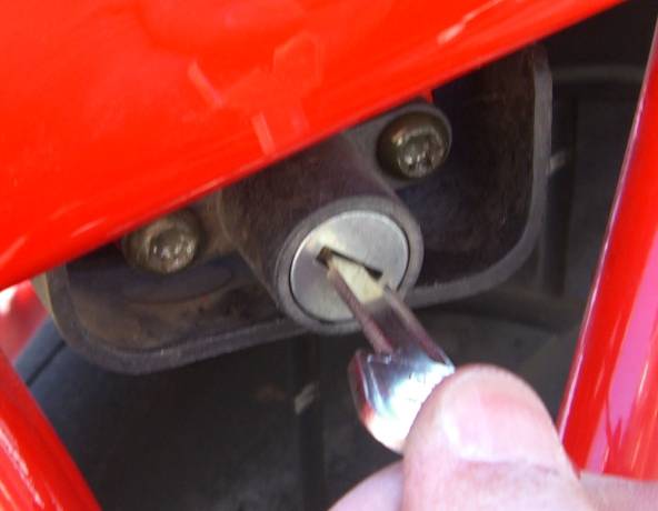
The reassembly and re-installation processes are the reverse of these procedures. The lock is shown, reinstalled, in figure 15, with the key in the unlocked position. The key rotates counter-clockwise to retract the seat latch.
 Figures 15 & 16
The cable-operated latch is shown in figure 16, as is the red helmet-holder hook. The helmet’s fastener rings can be placed over the hook under the left side of the bike before the seat is latched down. The helmet then can not be removed until the seat is unlatched and lifted out of the way.
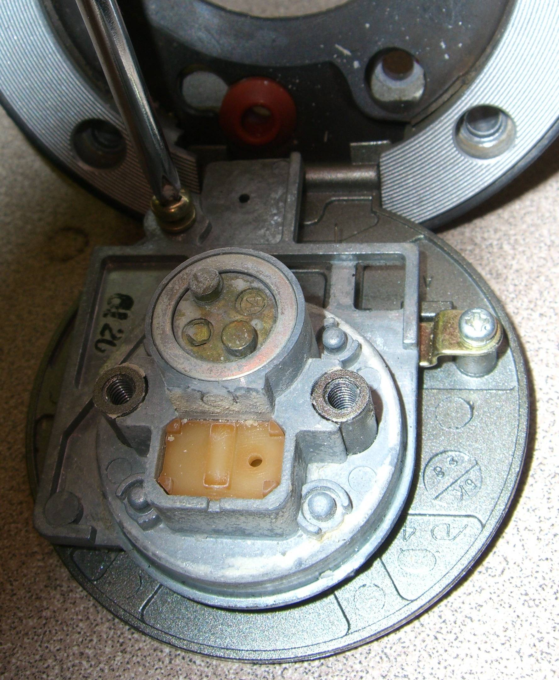
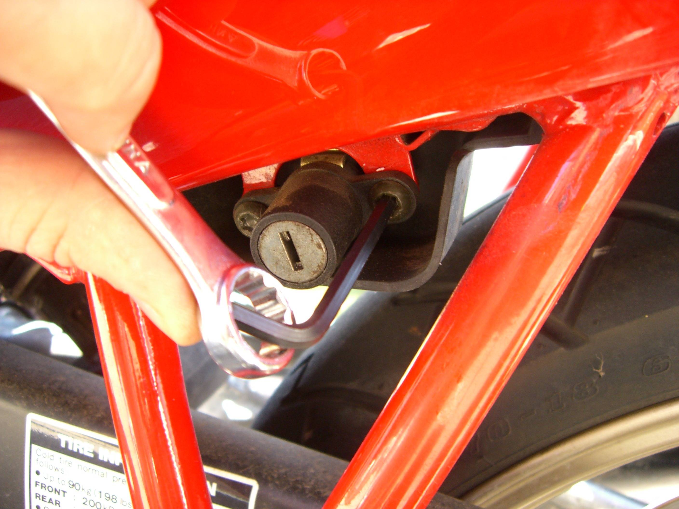
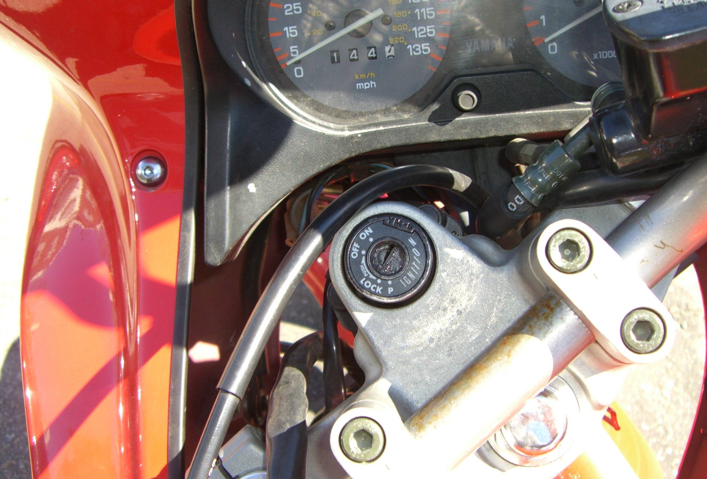
Ignition Lock
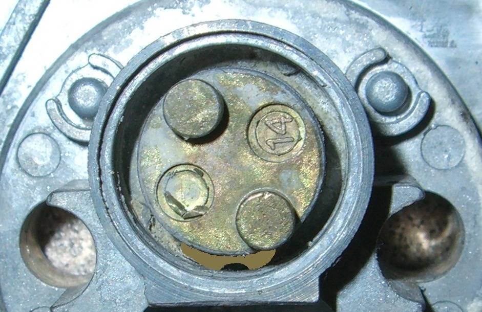
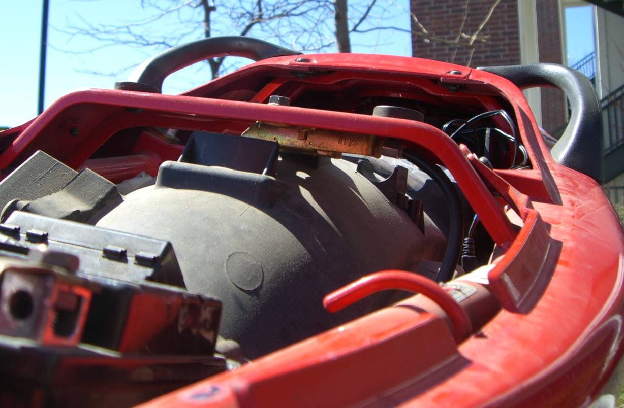
The ignition lock can be seen from the top in figures 17. The lock is marked with four positions: ON, OFF, LOCK, and P. The ON position turns on the lights and allows the engine to run. In any other position, the engine can’t run. In the LOCK or P position, the handlebars are locked to the left to prevent the bike from being wheeled away, or from being driven if hot-wired. The difference between these positions is that the P position turns on the parking-lights.
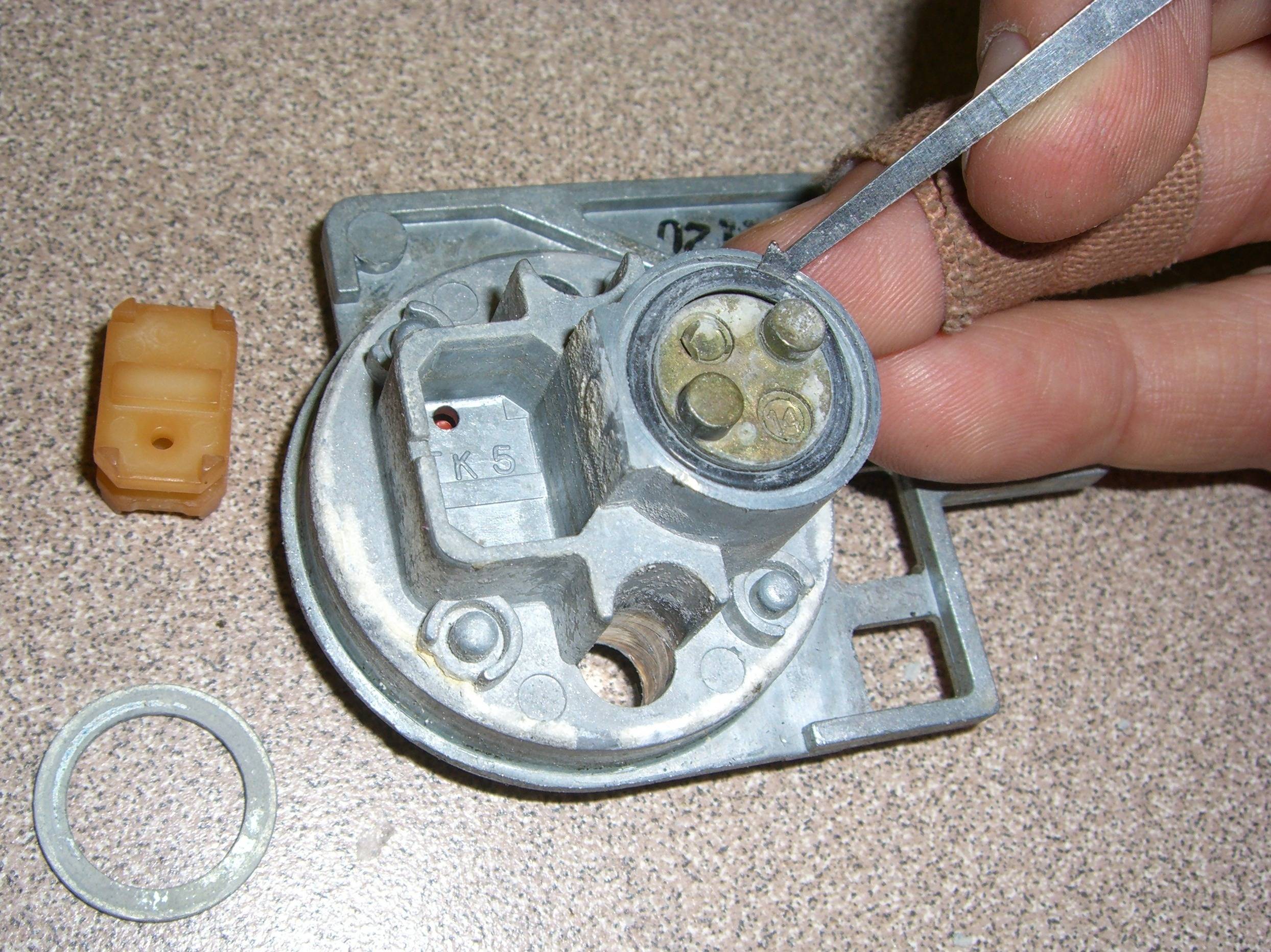
 Figures 17 & 18
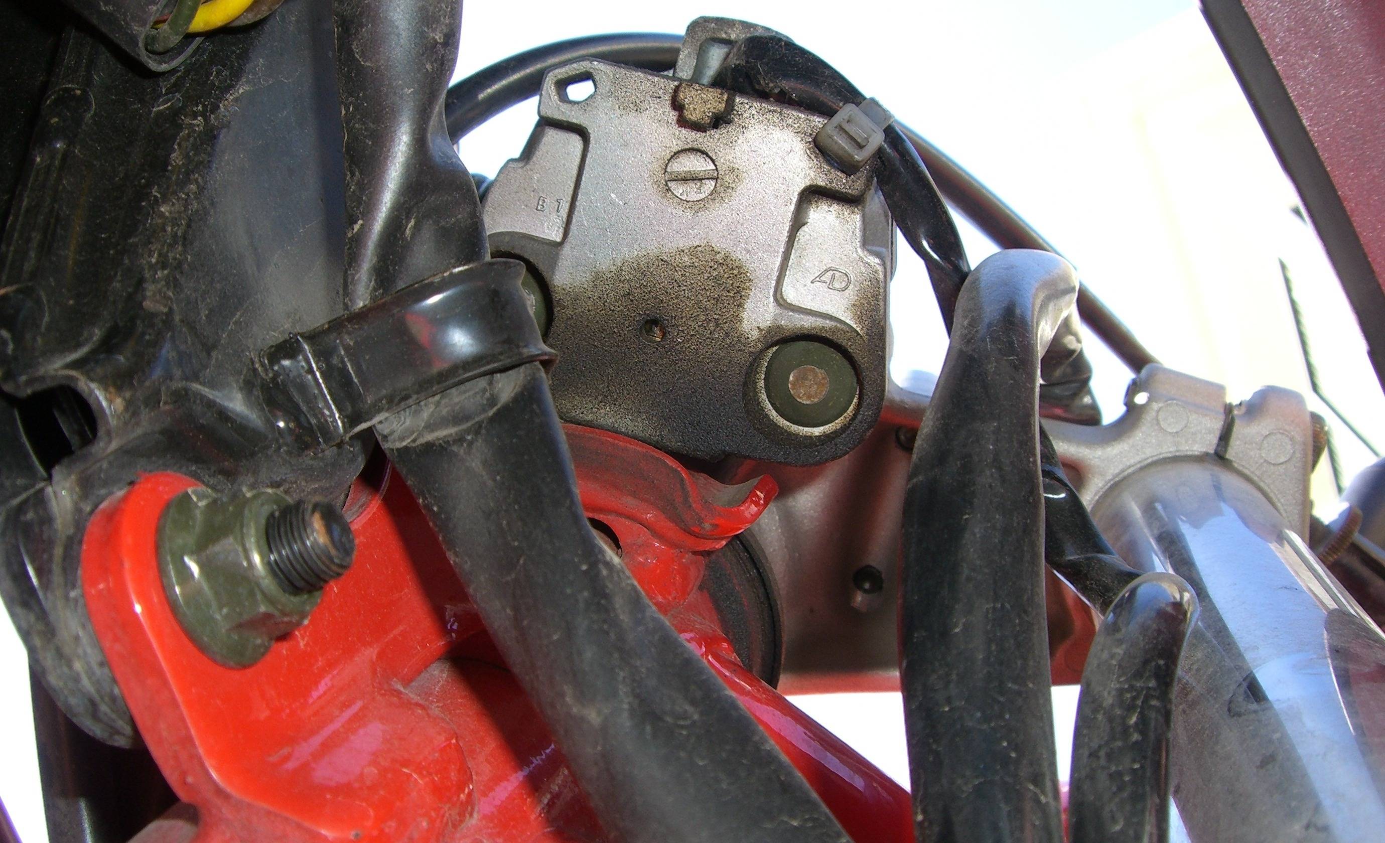
Figure 18 shows a bottom-view of this lock. It can be seen that the lock is attached with shear-head bolts. When the locks were installed at the Yamaha factory and these bolts were tightened down, the bolt-heads broke as they were designed to do. This is common on steering locks for cars and motorcycles alike. When I have to remove a lock that is attached with shear-head bolts, I either cut a screwdriver slot in each bolt with a small cut-off wheel in a Dremel rotary tool or unscrew them by tapping them around with a narrow chisel. But I rarely need to remove sportbike ignition locks.
When I need to make a key for a bike such as this, I usually start by making a key to either the gas-tank lock or the seat/helmet lock. This ignition lock uses the same key as those locks, but it uses two additional cuts of the key: the two cuts closest to the shoulder. With only two cuts to deal with, it’s a simple matter to determine their proper values through progression or impressioning.